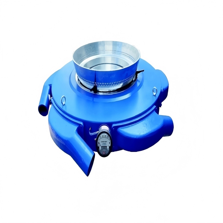
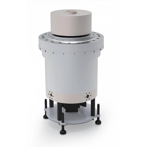
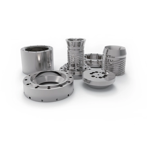
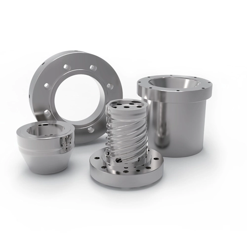
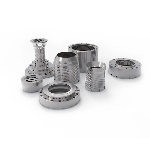
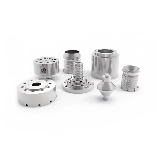
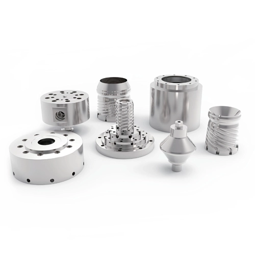
An air ring influences film gauge by controlling how evenly and how rapidly the molten bubble is cooled after it leaves the die. Uneven airflow, poor centering, unstable blower delivery, contaminated air passages, or interaction with ambient drafts can create local differences in bubble cooling and drawdown. These differences may appear as repeating thick and thin areas even when total extruder output remains stable.
However, not every gauge problem should be blamed on the air ring. Effective troubleshooting requires separating cooling-related variation from die-flow imbalance and upstream melt-pressure instability.
How Does an Air Ring Affect Film Thickness?
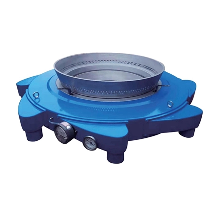
The blown film air ring directs cooling air around the molten tube as it expands above the die. The objective is not simply to deliver as much air as possible, but to create a stable and circumferentially uniform cooling field.
Local cooling differences affect melt strength, bubble shape, frost-line position, and the way the film is drawn before solidification.
If one section receives significantly different cooling from another, the resulting gauge profile may resemble a melt-distribution problem. This is one reason operators can spend considerable time adjusting the die without achieving a stable result.
Before making major die corrections, the air ring should therefore be checked for centering, level, cleanliness, and consistent airflow.
What Can an Uneven Frost Line Tell You?
The frost line is one of the most useful visual indicators available to a blown film operator.
A relatively stable frost-line height around the bubble suggests that the film is reaching its solidification region under reasonably consistent conditions. A frost line that is visibly higher on one side, lower on another, or constantly moving indicates that something is disturbing thermal or bubble stability.
The cause may be the air cooling ring, but die temperature, melt distribution, external drafts, bubble geometry, and internal bubble cooling can produce similar symptoms.
Observation
Possible Source
First Check
Frost line higher on one side
Uneven cooling or hotter melt zone
Airflow distribution and die temperature
Whole frost line moves vertically
Output, temperature or blower variation
Trend melt pressure and cooling air
Bubble oscillates sideways
Draft, air imbalance, cage setup
Ambient airflow and ring centering
Gauge band remains in fixed position
Die or stationary cooling imbalance
Map band position around bubble
Layflat width repeatedly expands/contracts
Bubble pressure or IBC instability
Bubble-size control and air system
The important point is that frost-line behavior should be compared with thickness data, not observed in isolation.
Does More Cooling Air Always Improve Film Stability?
No. Increasing cooling airflow can raise production capacity when the existing cooling system is the actual bottleneck, but excessive or poorly controlled air can make the bubble less stable.
More air changes the forces acting on the bubble and can move the frost line closer to the die. If airflow is not uniform around the circumference, increasing blower speed may amplify an existing imbalance instead of correcting it.
Airflow should therefore be matched to resin type, melt temperature, die diameter, output, blow-up ratio, film gauge, and bubble geometry.
Different air ring uses also place different demands on airflow design. A setup optimized for one film thickness and output range may not maintain the same stability when the line moves to a substantially thinner film or higher throughput.
The right cooling system provides enough heat-removal capacity while maintaining controllable airflow over the entire useful production window.
How Can You Tell Whether Gauge Variation Comes from the Air Ring or the Die?
Start by looking at how the defect behaves rather than immediately adjusting hardware.
A stable thick or thin band can originate from either the die or stationary air-ring geometry. Compare the gauge location with frost-line height, airflow condition, die-temperature zones, and melt-pressure trends.
If average gauge changes together with upstream pressure, screw output, or feeding fluctuations, the problem is unlikely to be solved by local air-ring adjustment.
If melt pressure is stable but frost-line shape changes and the gauge profile changes with it, cooling deserves more attention.
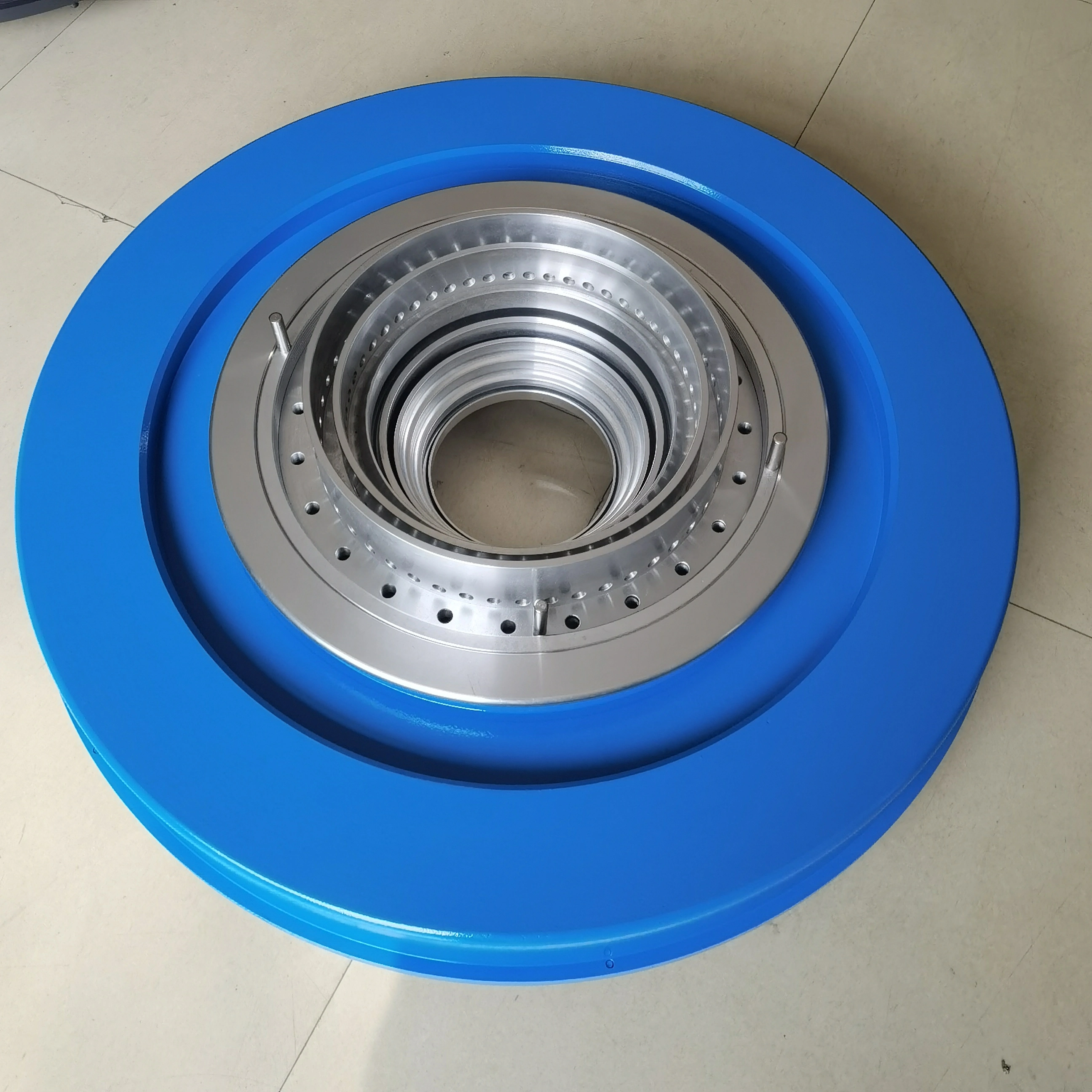
The interface between the air ring and the blown film die also matters. Poor centering between the components can create an apparently circumferential process problem even when both components perform acceptably on their own.
For this reason, mechanical alignment should be verified before trying to compensate with uneven airflow or repeated die-lip corrections.
What Maintenance Problems Commonly Disturb Air Ring Cooling?
Air rings often deteriorate gradually rather than failing suddenly.
Dust, polymer residue, or other contamination can alter small flow passages. Flexible air connections can loosen or leak. Diffusers can become partially blocked. Mechanical work around the die can also leave the air ring slightly off-center or out of level.
The resulting airflow difference may be small enough that operators cannot easily see it but large enough to influence thin-film production.
Blower performance should also be monitored. A nominal blower speed does not guarantee that delivered airflow remains constant if filters, ducts, valves, or other restrictions change.
Production records are useful here. If a line previously produced acceptable gauge at a particular recipe but gradually requires more operator intervention, inspection and cleaning should come before major recipe changes.
What Data Should Be Provided When Selecting or Upgrading an Air Ring?
A useful air-ring inquiry includes more than the die diameter.
The supplier should understand the polymer or polymer range, die diameter, die-lip dimensions, typical and maximum output, film width or bubble diameter, target film thickness, blow-up ratio, frost-line operating range, blower configuration, and whether internal bubble cooling is used.
It is also valuable to explain the actual production problem. A line limited by cooling capacity requires a different solution from a line that already has sufficient cooling but suffers from circumferential gauge variation.
Providing current bubble photographs, frost-line observations, gauge-profile data, and basic operating conditions can make equipment selection considerably more accurate.
Conclusion
Stable air-ring cooling is a prerequisite for repeatable blown film gauge, but cooling should be treated as one part of the complete extrusion system. Uniform airflow, correct mechanical alignment, steady blower performance, a stable frost line, consistent melt delivery, and balanced die flow must work together.
When gauge variation appears, avoid compensating for several possible causes at once. Compare the thickness pattern with melt pressure, frost-line behavior, bubble movement, and fixed machine positions. Identifying whether the disturbance originates upstream, at the die, or in the cooling system leads to faster corrections and a more repeatable production window.
FAQ
1.Can an air ring cause uneven film thickness?
Yes. Circumferential airflow differences can change local cooling and bubble drawdown, creating repeating gauge variation even when extruder output is stable.
2.Why does the frost line keep moving up and down?
Changes in extrusion output, melt temperature, cooling airflow, ambient conditions, or bubble-control behavior can move the frost line. The relevant variables should be trended together before making adjustments.
3.Should I adjust the die when one side of the film is thicker?
Not immediately. First check whether the gauge pattern is associated with uneven air-ring cooling, frost-line tilt, alignment, or upstream pressure variation. Die adjustment is most effective after these other causes have been separated.

 English